Here is the truth table for the Exclusive-Or (or "exactly-one") function (XOR):
A  B  |  Out
------|----
0  0  |  0
0  1  |  1
1  0  |  1
1  1  |  0
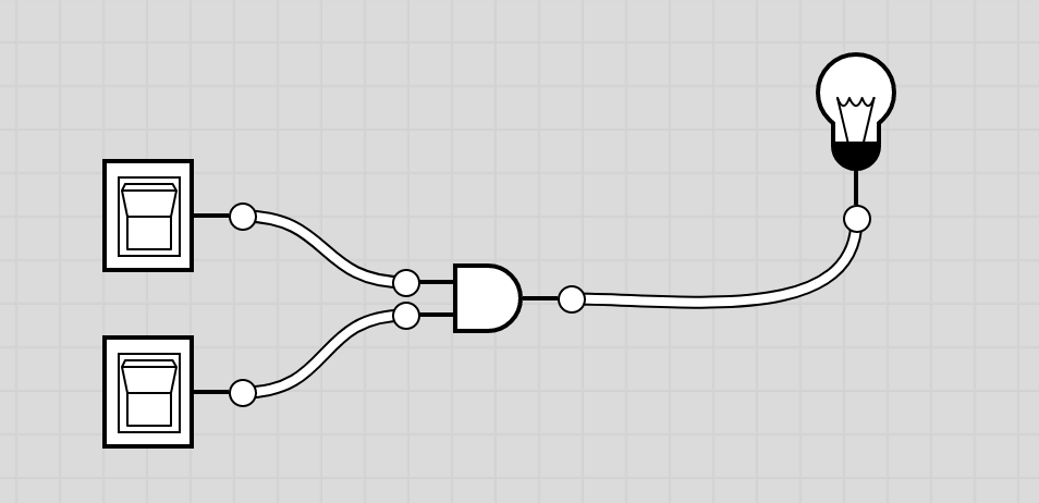
In the previous Circuit Diagrams assignment you identified 2 different Boolean expressions and circuit diagrams that implement the logic of the XOR function. Choose one of them and implement your expression using AND, OR, and NOT gates in Logicly. (In other words, do not use the built-in XOR gate.) Test your circuit to make sure that it generates the appropriate output for all possible inputs.
Saving your work: You can take screenshots to capture circuit diagrams and copy them into a single document or save them as separate files to zip up later. Alternatively, if you have downloaded Logicly to your own machine, you can go to File->Save As to save your files. (Kit will accept a PDF or a zip file for this assignment.)
- Screenshot on a mac: Press Shift + Command + 4, then move the crosshairs to where you want to start the screenshot, and then drag them to select the area you want to capture. It will save the screenshot in a .png on your desktop.
- Screenshot on a PC:
- Follow these instructions to Use Snipping Tool.
- Open a Word document. Go to the Insert menu, choose to insert a screenshot, and either choose a shot that it available, or choose to select an area of the screen to insert in your document.
- Follow one of these suggestions to take a screenshot.
A "half-adder" adds two 1-bit numbers and produces 2 bits of output. The first bit, known as the "carry bit", is 0 except in the case of 1 + 1 = 10. The second bit is known as the "sum bit" (even though, technically, the actual sum is both bits together).
Below you can see the four possible results from adding two bits (X and Y) as well as the truth tables for the sum and carry bits. Note that the truth table for the sum bit is the same as the Exclusive-Or (XOR) operation you have seen before, and the truth table for the carry bit is just an AND operation.
                                    Truth Tables for Sum and Carry Bits
        Addition of 2 bits:
       --------------------            X   Y   Carry     X   Y   Sum
                                      -------|-------   -------|-----
   X:     0    0    1    1             0   0 |   0       0   0 |  0
   Y:     0    1    0    1            -------|------    -------|-----
         --   --   --   --             0   1 |   0       0   1 |  1
         00   01   01   10            -------|------    -------|-----
                                       1   0 |   0       1   0 |  1
                                      -------|------    -------|-----
                                       1   1 |   1       1   1 |  0
In Logicly, build a circuit diagram for a half-adder that has two inputs and two outputs (the sum bit and the carry bit). Test that your circuit implements the truth tables above.
Side Note: Why is it called a "Half-Adder"?The addition function in the Arithmetic/Logic Unit (ALU) is implemented as a chain of 1-bit adders. (Full adders, not half-adders.) To add 32-bit numbers, for example, an ALU would chain together 32 1-bit adders. Each adder adds together 2 bits (1 bit from each operand) plus the carry (if there was one) from the previous adder.
A half-adder does approximately half the job of a full adder, adding just the 2 bits from the operands and ignoring the possibility of a carry from the previous bit.
Hint: Your Boolean expression probably included AND clauses with three terms. For example: A'B'C.
(IF YOU HAVE TIME) For this exercise build a "half-subtractor," as specified in the truth tables below. Like a half-adder, the half-subtractor has 2 inputs (X and Y) and 2 outputs, the amount and whether it is negative or not.
                                  Truth Tables for Neg? and Amount
     Subtraction of 2 bits:
     ----------------------         X   Y   Neg?      X   Y   Amount
                                   -------|-------   -------|--------
   X:     0    0    1    1          0   0 | 0 (F)     0   0 |   0
  -Y:    -0   -1   -0   -1         -------|------    -------|-------
         --   --   --   --          0   1 | 1 (T)     0   1 |   1
          0   -1    1    0         -------|------    -------|-------
                                    1   0 | 0 (F)     1   0 |   1
                                   -------|------    -------|-------
                                    1   1 | 0 (F)     1   1 |   0