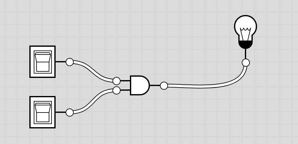
Here is the truth table for the Exclusive Or (or "exactly-one") function (XOR):
A  B  |  Out
------|----
0  0  |  0
0  1  |  1
1  0  |  1
1  1  |  0
Write a Boolean expression that corresponds to this truth table, and implement your expression using AND, OR, and NOT gates in Logicly. (In other words, do not use the built-in XOR gate.) Test your circuit to make sure that it generates the appropriate output for all possible inputs. For this exercise you will hand in your Boolean expression as well as a print-out or drawing of your circuit.
Saving your work: If you have downloaded Logicly to your own machine, you can go to File->Save As to save your file. If you are running Logicly through the browser, you cannot save the circuit board as a file, but you can take a screenshot to capture your circuit diagrams.
- Screenshot on a mac: Press Shift + Command + 4, then move the crosshairs to where you want to start the screenshot, and then drag them to select the area you want to capture. It will save the screenshot in a .png on your desktop.
- Screenshot on a pc:
- Follow these instructions to Use Snipping Tool.
- Open a Word document. Go to the Insert menu, choose to insert a screenshot, and either choose a shot that it available, or choose to select an area of the screen to insert in your document.
- Follow one of these suggestions to take a screenshot.
Hint: Your Boolean expression will probably include AND clauses that include three terms. For example: A'B'C.
For this exercise you will hand in your truth table, your Boolean expression, and a print-out or drawing of your circuit.
(IF YOU HAVE TIME) During class we worked through the design of a binary adder. The first step was to build a half adder, a circuit that could add two bits together as long as there was no carry-in from a previous add. For this exercise you will build a half subtractor, a circuit that can subtract two bits as long as there is no borrow from a previous pair of bits. Build and test a circuit that implements the following truth tables:
                                  INPUTS           INPUTS
    Subtraction of 2 bits:         X   Y  Result    X   Y  Borrow
    ----------------------        -------|------   -------|------
                                   0   0 |  0       0   0 | 0 (F)
   X     0    0    1    1         -------|------   -------|------
  -Y    -0   -1   -0   -1          0   1 |  1       0   1 | 1 (T)
        --   --   --   --         -------|------   -------|------
 Result: 0    1    1    0          1   0 |  1       1   0 | 0 (F)
 Borrow? F    T    F    F         -------|------   -------|------
			           1   1 |  0       1   1 | 0 (F)